It could be that ELEC 2501 is using the computer room - in this
case we hope to leave you a note by the door telling you where
the TA will be stationed - possibly in the computer room close
to the elevator or MC 6030
Since Nov 23, 24, 25 would normally be lab days, a TA will be
available from about 10AM in the computer room across from the
lab on each of those days. So, if you want to take advantage
of this lab time slot, and do your oscillator SPICE assignment,
or have any other questions for the TAs, you can take advantage
of this opportunity.
As announced in class, (Thur. Nov 10) Lab 3 due date is now 5
days later, that is, labs are now due on Mon Nov 21, Tue Nov
22 and Wed Nov 23.
For Assignment 3, to be handed out in class, You will need to
copy and modify the following two programs for oscillator analysis.
Your aim will be to achieve a particular output frequency and
power, and being approximately impedance matched. So, what you will
need to change:
Frequency determining components: C1, C2 (LT is given)
Load Resistance: RL
Resistor to represent transistor output resistance: RE4
(For open loop only)
Open loop: Frequency Range in .AC command to center on your frequency,
optimize curves
Closed Loop: Time range in .TRANS command to show rise time,
maybe zoom in to show a few periods to allow frequency to be
calculated. Make sure where you zoom in, the output voltage
is completely settled.
Notice: Assignment two help can be found in the Question list - link
back to 2004, 2003. E.g, What to do about 3 equations four unknows? How
to deal with 2.5 V?
SPICE File For mixer
This is not required for the lab, but you may find it interesting
and useful. Note, this is a nonlinear circuit, so simulations
are in the time domain. Tos see output spectrum including harmonics
and intermodulation components, run the fft on the output transient
waveform. Note that for this simulation, discrete 2N3904 transistors
have been used, but in spite of this, the results are quite realistic.
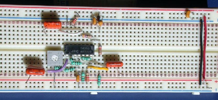
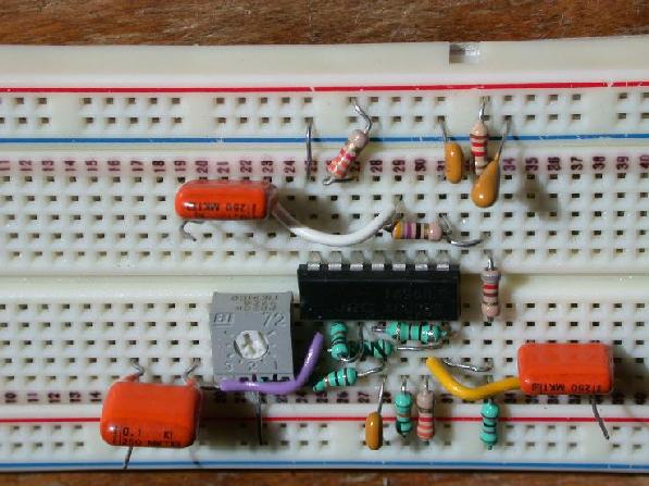
Photo of a Neatly Constructed
Mixer Board. Note that pin 7 has been used as an interconnect
point. It is labelled on the diagram as NC for No Connect. Often
it is not a good idea to use such pins, but in this case it seems
to work. (I still wouldn't do it though.) Also, note the yellow
wire hides a connection. Don't believe it?
Check out this picture from a different angle.
TAs: Peter Popplewell, ppopp@doe.carleton.ca, Tony
Forzley, tforzley@doe.carleton.ca
Office Hours: C. Plett Mon, Wed, 11:30-12:30, TAs, TBD
Course Objective
To learn about the design of
communications circuits. In other courses, the block diagram
approach has been used but in this course the emphasis will be
on the actual circuitry which makes up these blocks. Examples
of such blocks are tuned amplifiers, mixers, oscillators, phase
shifters and detectors. Communications systems considered are
AM, FM, television and telephony. Use of the PLL will be discussed.
Course Content
Introduction to Telecommunications:
Components of a radio systems; noise, distortion impedance matching.
Mixers and Modulators:
Phase-Locked Loop and Applications:
Introduction to PLLs and applications such as:
synthesizers and FM demodulation.
Oscillators:
Frequency modulators and demodulators:
Television Systems:
Transmission of intensity, color, retrace, blanking, and sound;
generation of the video signal, conversion of the video signal
to picture and sound. Other topics may include high-definition
TV, stereo sound.
Labs
Simulation Labs - Groups of 1; Hardware Labs - Groups of 2, one
writeup per group, due one week after the scheduled lab day, 4:30 PM.
Tuned Amplifiers: (Dates tentative)
(Warmup on September 15, 16, 17 actual lab on 29, 30, October
1). Simulation Lab. Use of a bipolar transistor and some passive
components to build a tuned amplifier operating at about 1MHz.
You will learn about use of transistor parameters, tuned circuits
and impedance matching.
Mixers and Modulators:
(October 13, 14, 15) Use of an analog multiplier on an IC to
build frequency changers.
Phase-Locked Loops:
(October 27, 28, 29 and November 10, 11, 12) Use of a commercially
available package to build a tracking filter, a synthesizer and
a an FM demodulator. The IC contains a voltage-controlled oscillator
a phase detector, and amplifiers. In this lab, the VCO and phase
detector will be characterized, then a complete phased-lock loop
will be built. The main external components will consist of a
simple loop filter and a divider to realize the synthesizer.
Marks:
a) Three assignments worth 5% each
b) Three Labs worth 10, 10,15 (about 1/3 for demo)
c) One written exam worth 50%.
**** Students must get at least 35% in the final exam. ****
Text:
There is no official course text. The printed course notes should
provide enough material, or some of the references can be consulted.
References:
Smith,
"Modern Communication Circuits", Second Edition McGraw-Hill 1998, TK6553.S5595
Krauss, Bostonian, Raab,
"Solid State Radio Engineering", Wiley 1980, TK6553.K73
Rogers and Plett,
"Radio Frequency Integrated Circuit Design", Artech House 2003
Hagen,
"Radio Frequency Circuit Design", Cambridge Press, 1997
William F. Egan,
"Frequency Synthesis by Phase Lock", 2nd Ed. John Wiley & Sons,
2000
Van der Puije,
"Telecommunication Circuit Design", Wiley 1992, TK5103.V