Review Session, Thursday Dec 13, 1:30-3:30 Room
4499ME.
I expect to solve problems, please respond with your requests
for the problem types below and I will list them as they come
in:
General Radio issues, NF, Distortion
tuned amplifier,
class C amplifier or frequency multiplier
PLL problem,
Review of Labs, Assignment problems
I have had a request to avoid doing more tuned amplfier questions,
instead do a bunch of the short answer questions and problems,
for example 1997 numbers 2 and 3.
Dec 10, 2001, Review Session is still being planned for Thursday
Afternoon, Time, early afternoon, Room not yet determined. Assignment
3, lab 3 marked. Marks are up on web page (see above). Marked
labs, assignments are available for pick up (if I am around,
possibly Wednesday) and I plan to bring them to the review session.
Nov. 5.Lab1, Assignment 1 have been marked.
They can be picked up in room ME5146. The remaining labs/assignments
will be brought to class, but if you can, pick them up to save
me having to carry them.
Lab 1 and Assignment 1 are
both due Tue Oct. 9, Wed Oct.10, Thur Oct. 11 for students who
did the lab on Wednesday, Thursday and Friday respectively. Note,
this only gives you one day to prepare for the next lab. Preparation
is important, so make sure you do it. New Addition:
As announced in class, hand in time is 11:30AM to give
time to prepare for Lab 2, and also because this way you can
hand it in to the TAs or to the prof in the class or in the lab.
Normally, hand in time would be at 4:30 one week after the lab
is done. Because this is a bit of a last-minute announcement,
we will understand if people are a a bit late.
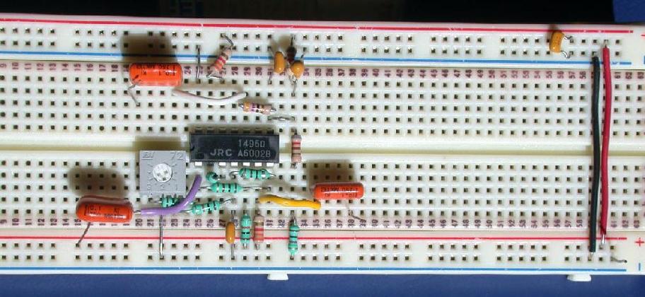
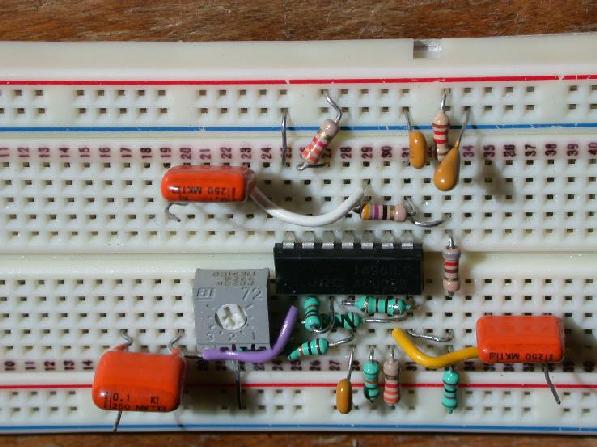
Photo of a Neatly Constructed
Mixer Board. Note that pin 7 has been used as an interconnect
point. It is labelled on the diagram as NC for No Connect. Often
it is not a good idea to use such pins, but in this case it seems
to work. (I still wouldn't do it though.) Also, note the yellow
wire hides a connection. Don't believe it?
Check out this picture from a different angle.
The following is from 2000, but will be similar this year.
Note: for Lab 1 and Assignment 1, frequency was 10.7 MHz last
year, it is 5.4 MHz this year. Similarly, bandwidth has changed
from 2 MHz last year to 1 MHz this year.
Lectures: MC5050
(Not in HP as was listed in the registration guide. It was changed.)
Times
Tue 11:30, Wed 13:30, Fri 12:30
Labs: ME4135, Wed, Thur, Fri, 8:30-11:30 even weeks
TAs: John Rogers, Bill Toole
TA Office Hours: TBD
Course Objective
To learn about the design of
communications circuits. In other courses, the block diagram
approach has been used but in this course the emphasis will be
on the actual circuitry which makes up these blocks. Examples
of such blocks are tuned amplifiers, mixers, oscillators, phase
shifters and detectors. Communications systems considered are
AM, FM, television and telephony. Use of the PLL will be discussed.
Course Content
Introduction to Telecommunications:
Components of a radio systems; noise, distortion impedance matching.
Mixers and Modulators:
Phase-Locked Loop and Applications:
Introduction to PLLs and applications such as:
synthesizers and FM demodulation.
Oscillators:
Frequency modulators and demodulators:
Television Systems:
Transmission of intensity, color, retrace, blanking, and sound;
generation of the video signal, conversion of the video signal
to picture and sound. Other topics may include high-definition
TV, stereo sound.
Labs
Simulation Labs - Groups of 1; Hardware Labs - Groups of 2, one
writeup per group, due one week after the scheduled lab day, 4:30 PM.
Tuned Amplifiers: (Dates removed, these were 2000)
(September ??, ??, ??). Simulation Lab. Use
of a bipolar transistor and some passive components to build
a tuned amplifier operating at about 1MHz. You will learn about
use of transistor parameters, tuned circuits and impedance matching.
Mixers and Modulators:
(October ??, ??, ??) Use of an analog multiplier on an IC to
build frequency changers.
Phase-Locked Loops:
(November ??, ??, ?? and ??, ??, ??) Use of a commercially available
package to build a tracking filter, a synthesizer and a an FM
demodulator. The IC contains a voltage-controlled oscillator
a phase detector, and amplifiers. In this lab, the VCO and phase
detector will be characterized, then a complete phased-lock loop
will be built. The main external components will consist of a
simple loop filter and a divider to realize the synthesizer.
Marks:
a) Three assignments worth 5% each
b) Three Labs worth 10, 10,15 (about 1/3 for demo)
c) One written exam worth 50%.
**** Students must get at least 35% in the final exam. ****
Text:
There is no official course text. The printed course notes should
provide enough material, or some of the references can be consulted.
References:
Smith,
"Modern Communication Circuits", Second Edition McGraw-Hill 1998, TK6553.S5595
Hagen,
"Radio Frequency Circuit Design", Cambridge Press, 1997
Krauss, Bostonian, Raab,
"Solid State Radio Engineering", Wiley 1980, TK6553.K73
Van der Puije,
"Telecommunication Circuit Design", Wiley 1992, TK5103.V