Inductor Q at 100 kHz and 1.2 MHz
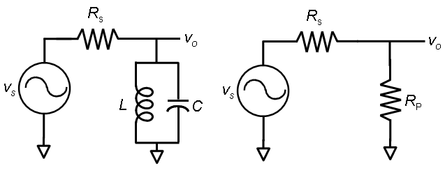
I measured some inductor Q's at 1.2 MHz - results: for 33 uH Q is 25-30, for 3.3 uH and 10 uH, Q is between 15 and 20. So, the 33 uH inductor has the highest Q, but it is no longer as drastically a difference as at 100 kHz where 100 uH has a Q of 7 to 8, and the 3.3 and 10 uH inductors have a Q of about 2 to 3. Measurement technique: place the inductor L parallel to a capacitor C so that resonance is close to 1.2 MHz, add a series resistor Rs and apply a signal at the resonance frequency. The Inductor has parallel resistor Rp which at resonance forms a voltage divider with Rs - knowing Rs and measuring the input voltage and the across across Rp, the value of Rp can be determined. Example, for 33 uH, a 560 pF capacitor resonates close to 1.2 MHz. series resistance of 6.8k results in a voltage divider with gain of about 1/2, thus Rp is equal to Rs which is 6.8 k. Q is given by Rp /(omega x L) thus Q is 27. Since this inductor was measured at 100 kHz as having a Q of 7.9, it turns out the ratio of Q at 1.2 MHz to Q at 100 kHz is exactly the square root of 1.2M/100k. The smaller inductors seem to have a higher ratio - probably related to them being further from their maximum Q. At frequencies above the maximum Q frequency, Q will drop and go to zero at the self-resonance frequency. Note at low frequency it would be expected that series resistance would be constant and in such a case, Q would be proportional to frequency.
Measured Inductor Q at 1.2 MHz, 100 kHz
| Inductance | Capacitance | Resonance | Series R | Voltage | Parallel R | Q(1.2 MHz) | Q(100 kHz) | Ratio |
| 33 uH | 560 pF | 1.17 MHz | 6.8 k | 0.5 | 6.8k | 27 | 7.9 | 3.418 |
| 10 uH | 1.8 nF | 1.26 MHz | 1.364 k | 0.48 | 1.26 k | 15.9 | 2.1 | 7.57 |
| 3.3 uH | 5.6 nF | 1.17 MHz | 470 | 0.5 | 470 | 18.3 | 2.9 | 6.31 |
|
|
|